How to get an ASUS X99-A Motherboard to Accept an i7 6800K
After much research and verification, I purchased a bunch of components to upgrade my server:
- An ASUS X99-A motherboard
- An i7-6800K CPU
- 4x4GB Corsair Vengeance DDR4 (specifically a kit of CMD16GX4M4A2800C16)
- A new modular power supply (Corsair CX550M)
All of these components then sat in their boxes for more than a year, because I got busy and then forgot.
After putting them together, building everything into the case and screwing everything down, the status LED on the motherboard kept reading code 53. The manual tells me that that means “Memory initialization error. Invalid memory type or incompatible memory speed.”
Tracking down the cause
I started by taking out all but one stick of DDR4, trying it in multiple slots. Again, status code 53.
I tested that the RAM I had was working in another computer and I tried some known-good DDR4 from another computer (CMK16GX4M2B3000C15). Again, status code 53.
I looked up the Qualified Vendor List (QVL) table for the motherboard and both RAM and CPU were on there (https://www.asus.com/us/Motherboards/X99A/HelpDesk_CPU/).
However, the CPU was marked as only being support from BIOS version 3004 onwards (updated BIOS version available here: https://www.asus.com/us/Motherboards/X99A/HelpDesk_BIOS/). I couldn’t be sure, but based upon the last 4 of my sticker, I likely only had BIOS version 1004 (https://forums.tomshardware.com/threads/asus-x99-a-error-53-cannot-use-bios-flashback.3016607/)
Trying to flash the BIOS using ASUS Flashback
This motherboard (along with many recent ASUS boards) supports something called BIOS Flashback (https://forums.tomshardware.com/threads/asus-x99-a-usb-3-1-usb-flashback-bios.2755390/).
It allows the motherboard BIOS to be updated from USB key with neither a working CPU nor working RAM.
However, I couldn’t for the life of me get it to work - the flashback light would flash 4 times then go solid blue, indicating a failure. My understanding from reading online is that it should keep flashing for a couple minutes.
I verified that:
- I’d correctly renamed the downloaded BIOS file to the one listed here: https://www.asus.com/us/support/FAQ/1030124/
- I only had a single primary partition marked as active and non-bootable.
- I was inserting the USB key into the correct port (if I moved it to another port, it would instead flash 7 times, acting the same as when no USB key was inserted at all)
- Clearing CMOS made no difference (remove power from computer; remove onboard battery for 15s or more; move jumper to clear real-time clock; move jumper back; reinsert battery; power on)
Perhaps the version of the BIOS installed had some bug doing flashback?
After many hours, I gave up trying to do a Flashback.
I looked at buying an older CPU that was supported on this board from day 1 (i7 5820K or Xeon E5-1620v3.)
I saw that I could order a new BIOS chip that would come with the latest BIOS e.g.:
- https://www.ebay.com/itm/BIOS-CHIP-ASUS-X99-A-/380942685656
- http://www.bios-chip24.com/Asus-X99-A/USB-31/en
But perhaps there was another way?
Flashing the BIOS chip with a Raspberry Pi
The BIOS chip is just an EEPROM chip and can’t a Raspberry Pi program EEPROM chips? Why - yes it can!
Here’s a blog post on the process: https://tomvanveen.eu/flashing-bios-chip-raspberry-pi/
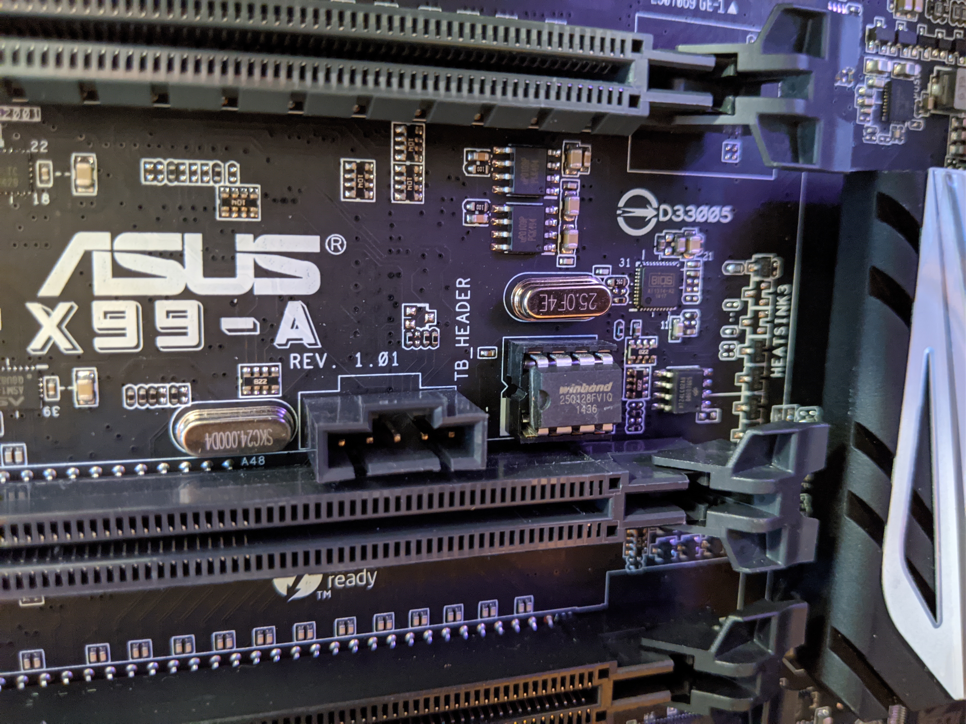
So I found the BIOS chip and tried to remove it from the motherboard (without the proper tool - obviously).

I got it loose, but one of the legs was badly bent. I crossed my fingers and bent it back into place.
I found the datasheet for the BIOS chip (https://www.winbond.com/resource-files/w25q128fv%20rev.m%2005132016%20kms.pdf) and compared that with both the article above and the Raspberry Pi GPIO documentation (https://www.raspberrypi.org/documentation/usage/gpio/), coming up with this table:
| RPi PIN | description | connection | PIN Name | Description | EEPROM PIN |
|---|---|---|---|---|---|
| 25 | Ground | GND | GND | Ground | 4 |
| 24 | SPI_CEO_N | CS | /CS | Chip Select Input | 1 |
| 23 | SPI_CLK | SCK | CLK | Serial Clock Input | 6 |
| 21 | SPI_MISO | DO | DO (IO1) | Data Output | 2 |
| 19 | SPI_MOSI | DI | DI (IO0) | Data Input | 5 |
| 17 | v3.3 | VCC 3.3V | VCC | Power Supply | 8 |
| 17 | v3.3 | /HOLD | /HOLD or /RESET | Hold or Reset Input | 7 |
| 17 | v3.3 | /WP | /WP | Write Protect Input | 3 |
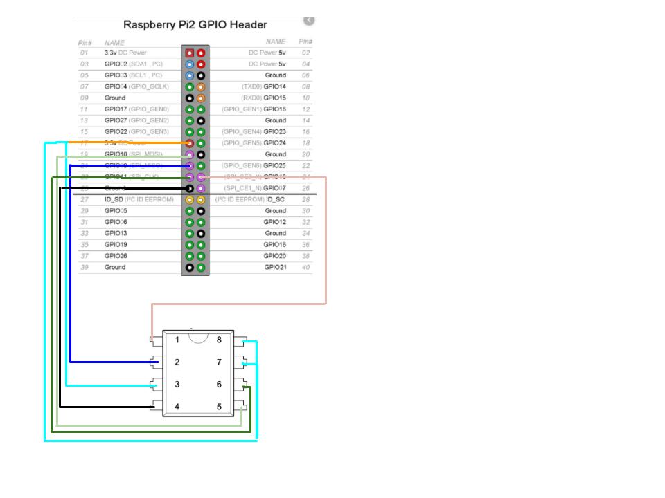
I then put together a diagram of what I was going to be connecting where:

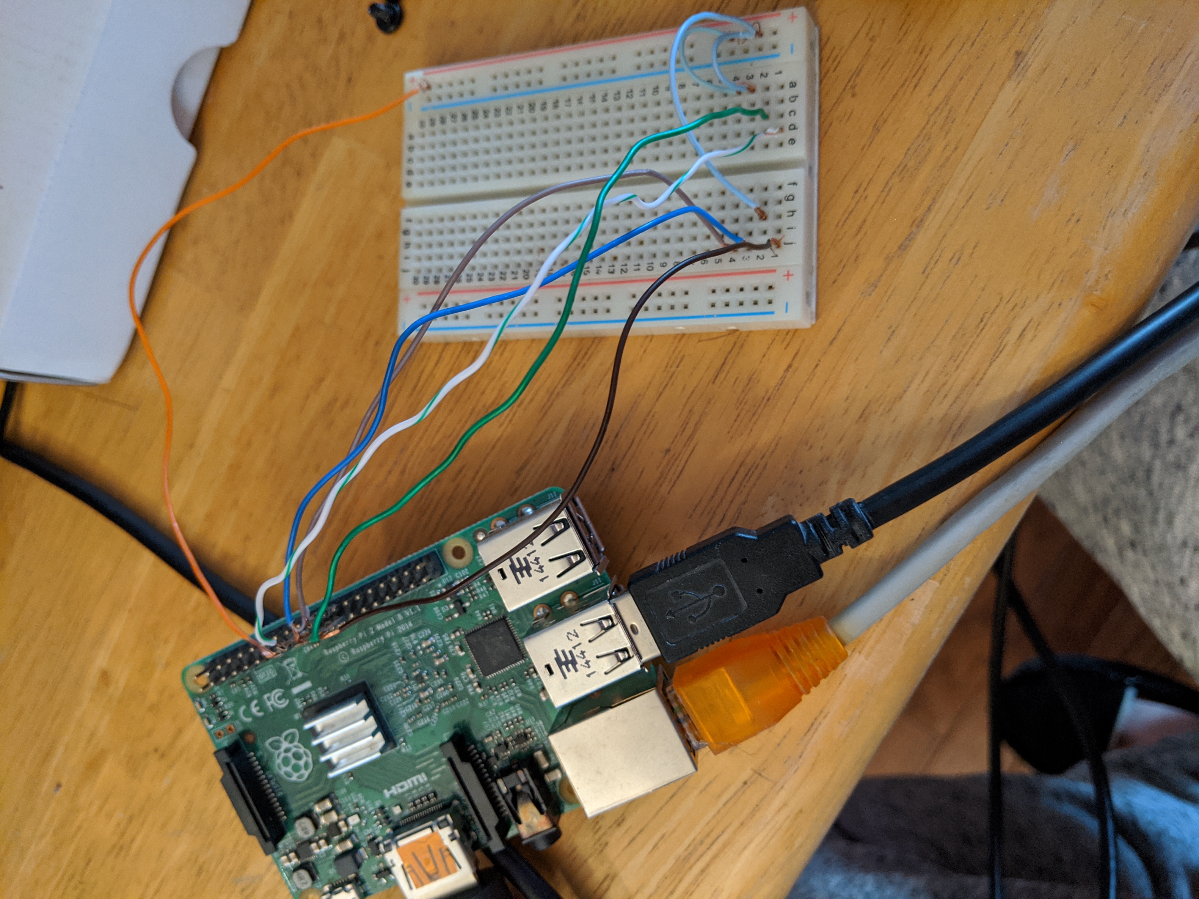
And finally put my breadboard together with the wiring:

Unfortunately, I didn’t grab a shot of the BIOS itself in this setup. The chip should span columns E and F from row 1 through 4 with the notch facing upwards.
I installed the flashrom utility (rather than following the article, I just ran sudo apt install flashrom)
So - we’re all set. I take the power away from the Pi, insert the chip, power it up and voila - it doesn’t work :-(
flashrom -p just gives me an error that I need to specify a programmer (later, I realize that I’ve misread the command in the article).
Out of the available programmers, linux_spi looks the most promising (I remember seeing it on the couple of the websites that I was reading about flashrom).
flashrom -p linux_spi then tells me that I need to specify a device.
flashrom -p linux_spi:dev=/dev/spidev0.0 detects that it is connected to an EEPROM chip, but can’t tell what it is.
After some more googling, I find that I need to restrict the speed.
flashrom -p linux_spi:dev=/dev/spidev0.0,spispeed=512 works a treat. It can tell me the type of chip I have and knows how to work with it.
Now back to the article - oh - now I see the working command was there all along - it’s just that linewrapping wasn’t kind to readability. Doh!
Finally, I think I’m ready, I read off the existing BIOS with flashrom -p linux_spi:dev=/dev/spidev0.0,spispeed=512 -r flash.dat. Note that it takes a couple minutes.
Looking at the filesizes though, it looks like my .CAP file is too large. After a little more googling, I find the answer in this StackExchange question (https://superuser.com/questions/678996/what-options-do-i-have-for-flashing-an-uefi-bios-chip-on-an-asus-mobo): The .CAP filetype has a CAP header of 2048 bytes.
Using the command from that question (dd bs=2048 skip=1 if=BIOS.CAP of=BIOS.BIN), I strip the CAP header and compare the filesizes again. They now match. Here goes nothing: flashrom -p linux_spi:/dev/spidev0.0 -w BIOS.BIN
After 10 minutes or so, it’s complete.
I reinsert the BIOS chip into the motherboard, and lo-and-behold, it ACTUALLY POSTS! Woot!
Moral of the Story
Perhaps don’t wait more than a year to use bits of computer you buy cause then you could just have RMAd it back to ASUS? Raspberry Pis are awesome? I don’t know - make up your own meaning.
